To Model in a Stringbag

With the cold weather, I moved the modeling inside rather than working in the garage so I decided to start work on the Swordfish.  I didn’t much care for the detail on the Heller Swordfish included in the box so I purchased three sets of L’Arsenal 1/400 Swordfish.  These are pretty good, missing only the TAG’s Lewis (or Vickers) machine gun, bombs, decals, crew and external fuel tanks.  You do get torpedoes!  You get a nicely detailed resin fuselage. For 1/400 scale, I could hardly complain.

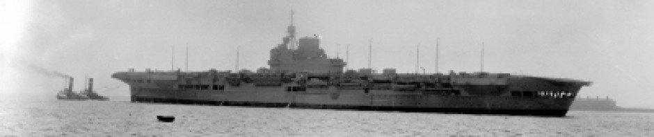
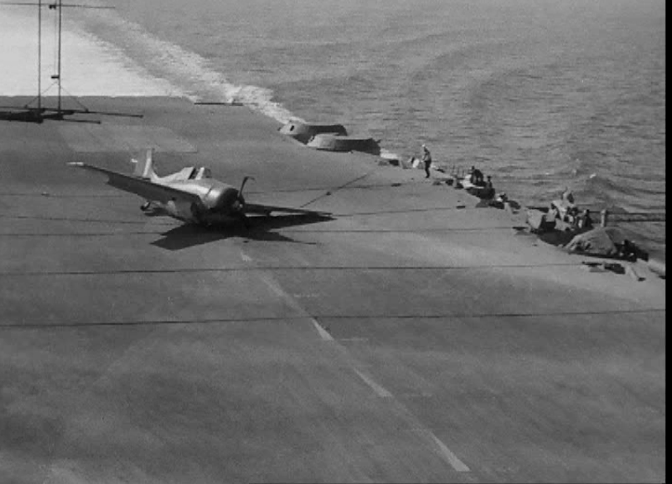
I decided that my diorama would depict my mother-in-law’s wartime boyfriend (Tony Wray) plane as it was taking off (number three in Wave 1) with thirteen planes from Waves 1 and 2 on deck and one plane from Wave 2 with wings folded coming up on the elevator.

A great resource for painting is Airfile Fairey Swordfish which has all the color profiles you will ever need. I was fortunate that a friend stumbled upon this at an airshow at Duxford in late May 2015.  Unfortunately for me, one of the four squadrons (Nr. 815) had a different camouflage scheme than the other three squadrons so this meant more variation in masking.

Building a biplane in 1/72 is hard enough but in 1/400, more thought was applied each night when I lay my head down to sleep (Dream Ideas!).  I decided that painting each PE component part on its fret and then decaling+sealing would be done before any assembly as masking would be nigh-on impossible once assembled.

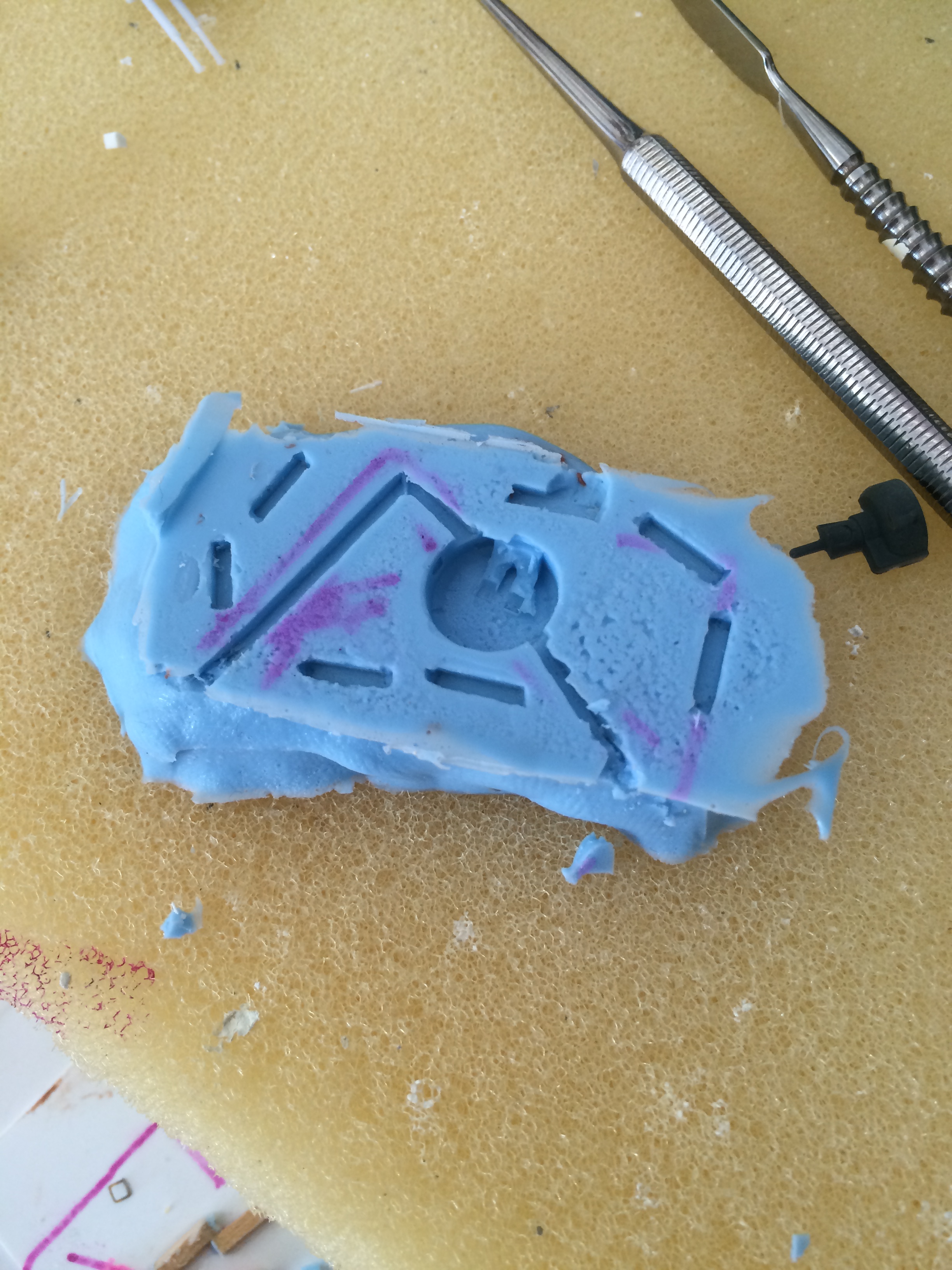
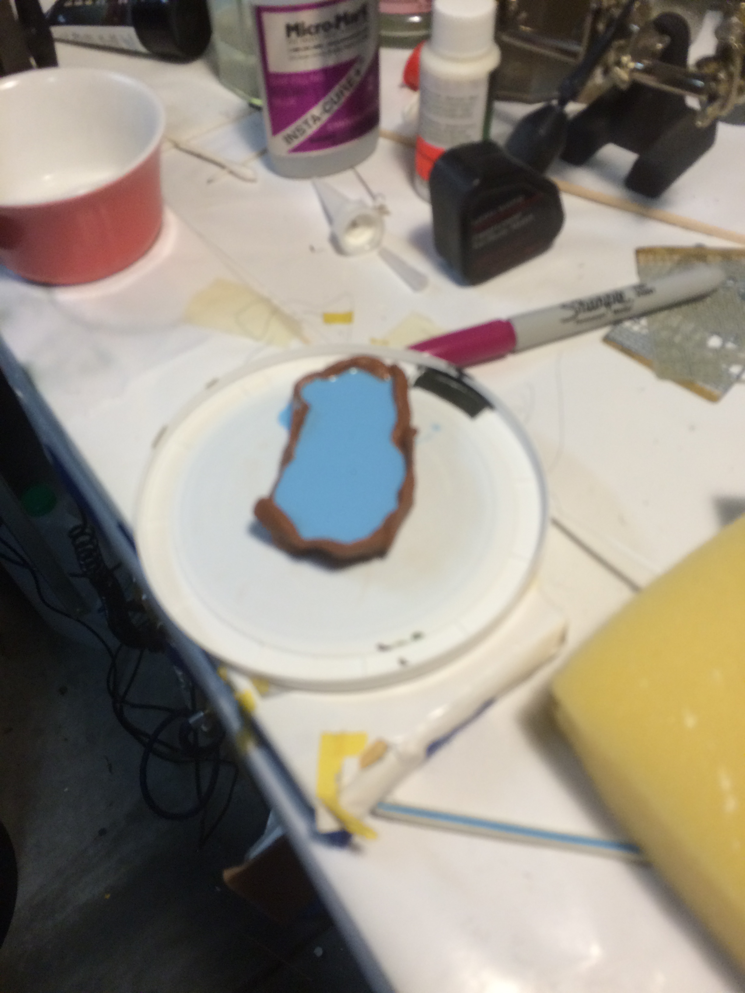
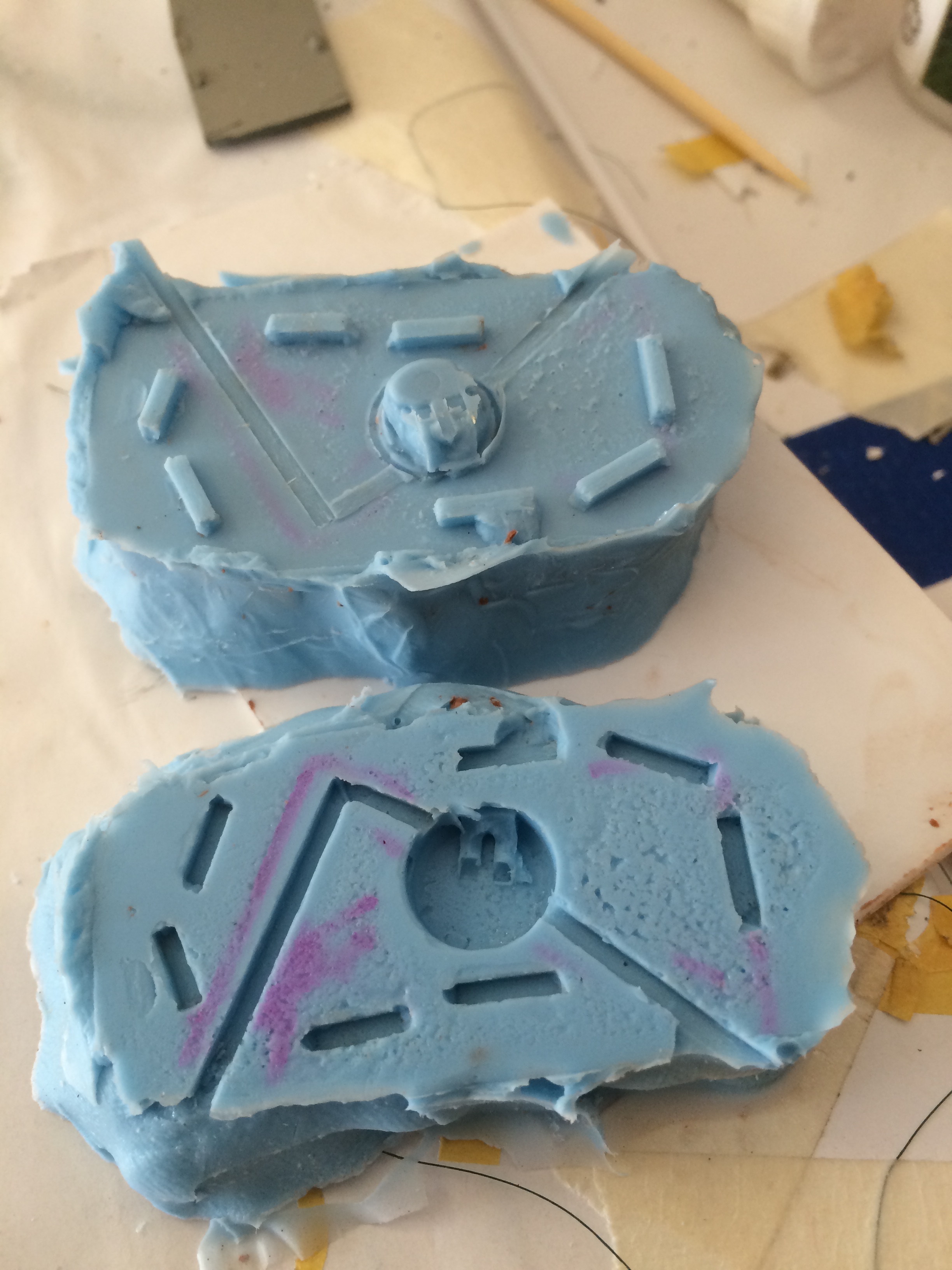
Here’s progress to date. First, masking with silly putty, and then with the putty removed. 815 Squadron is on the left of the rightmost photo. Click the p

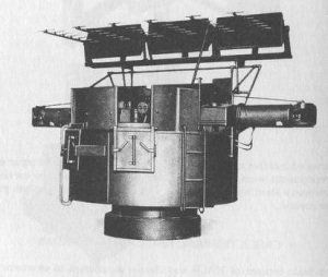
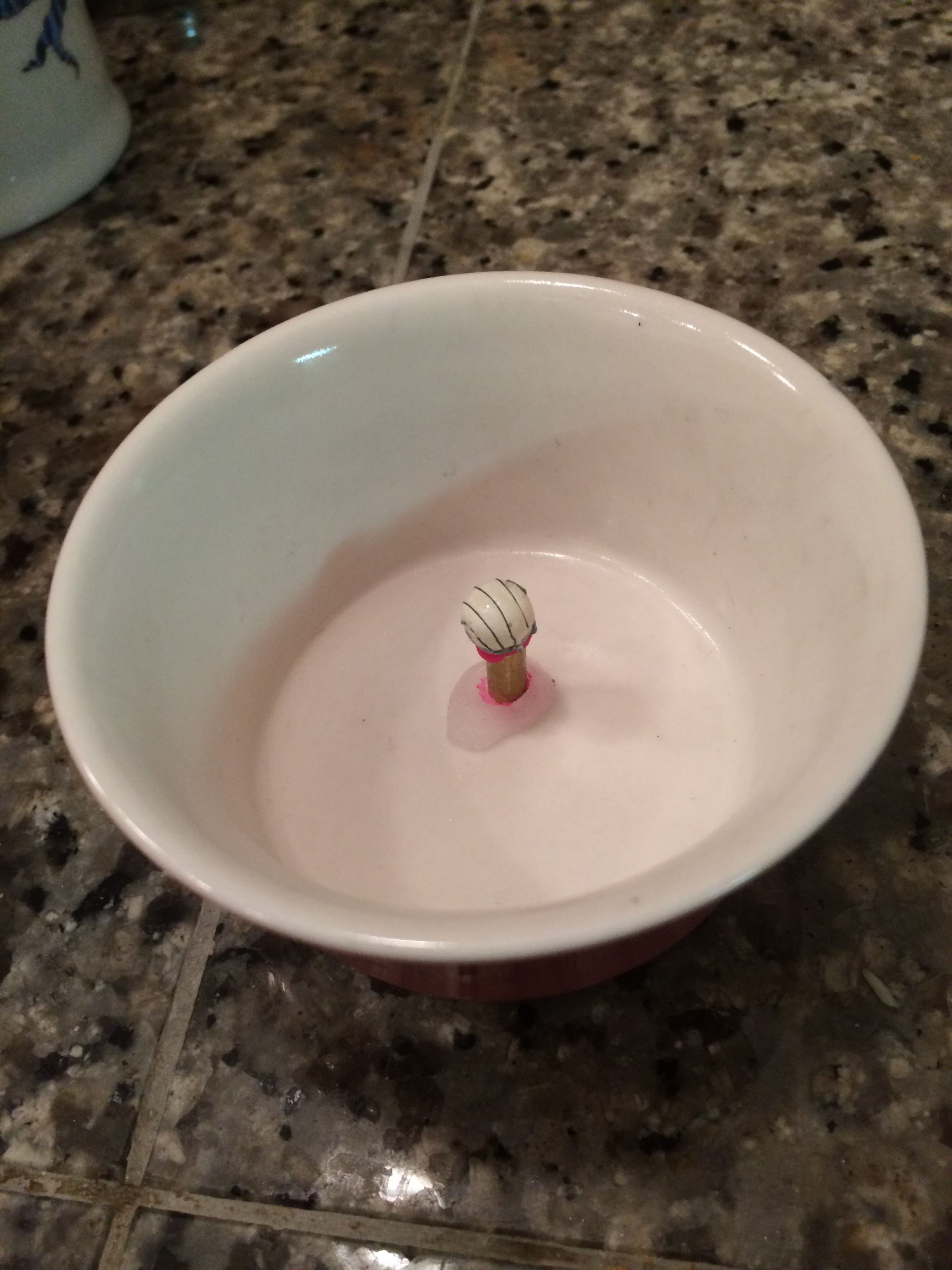
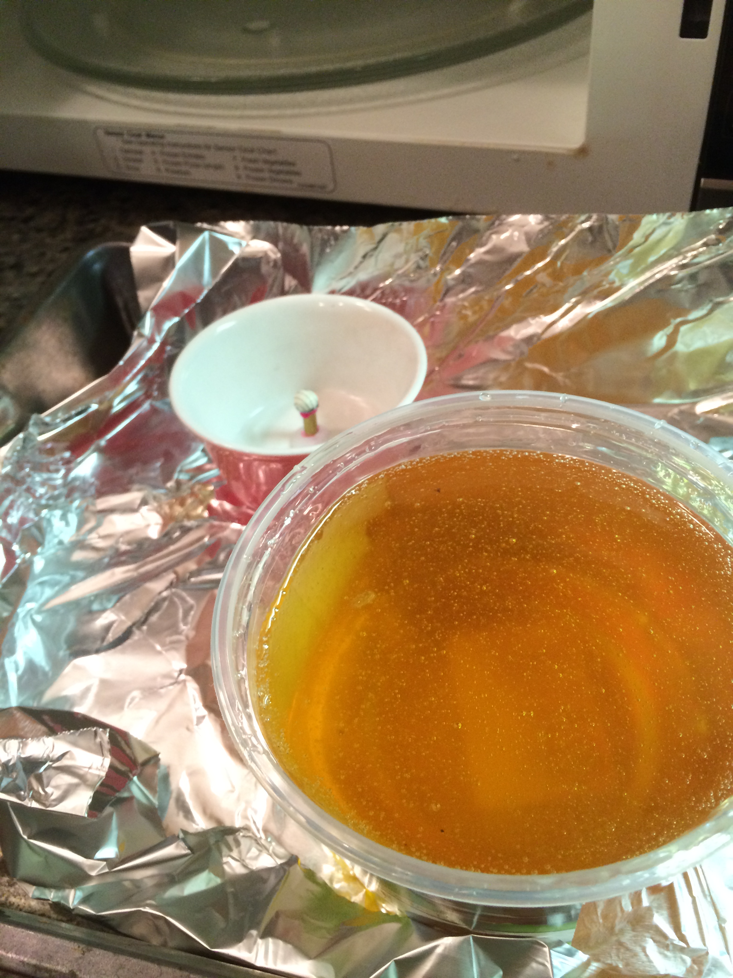
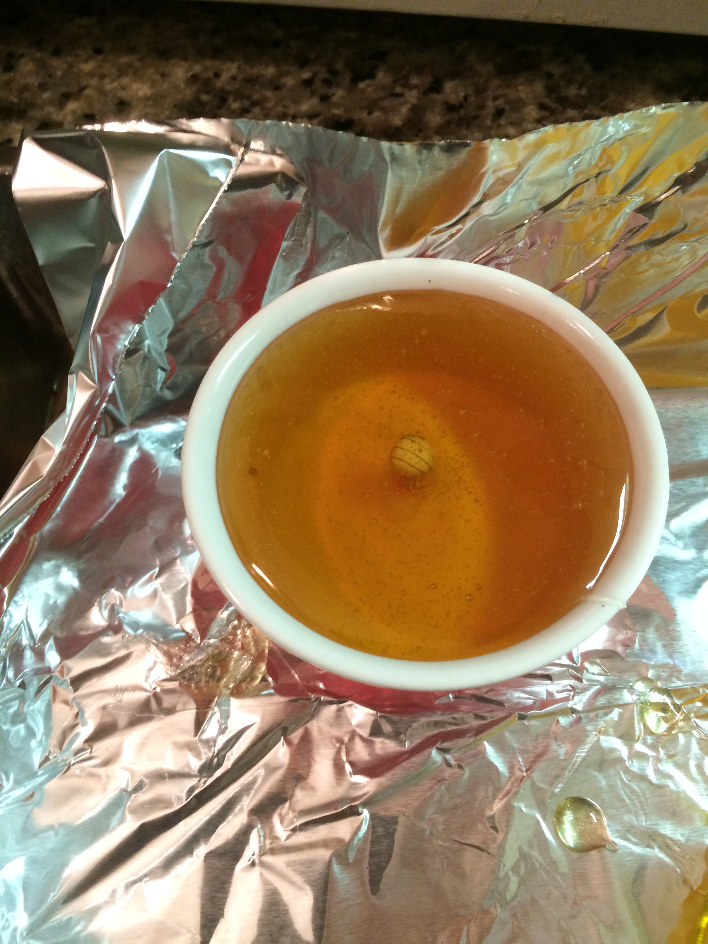
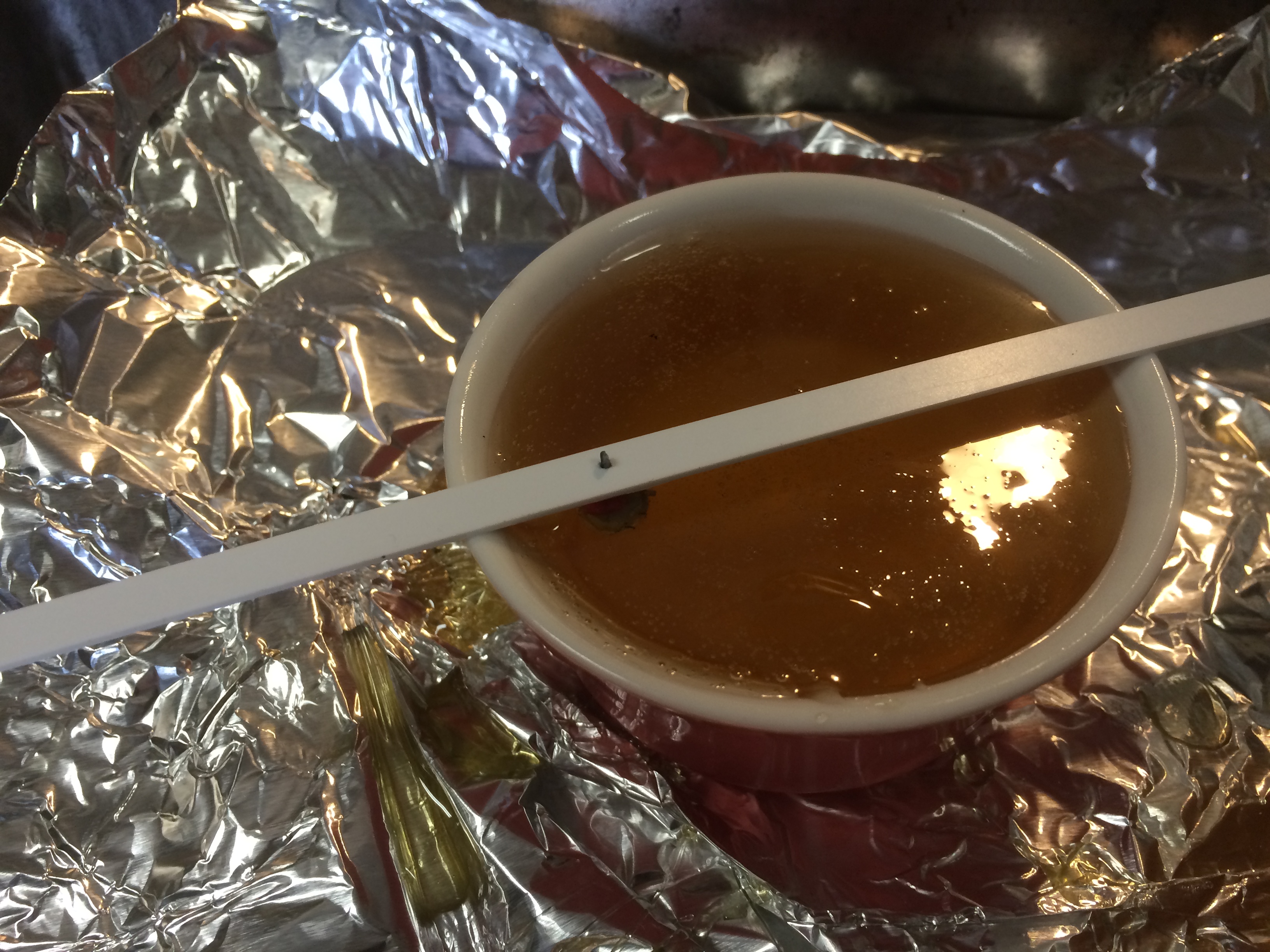
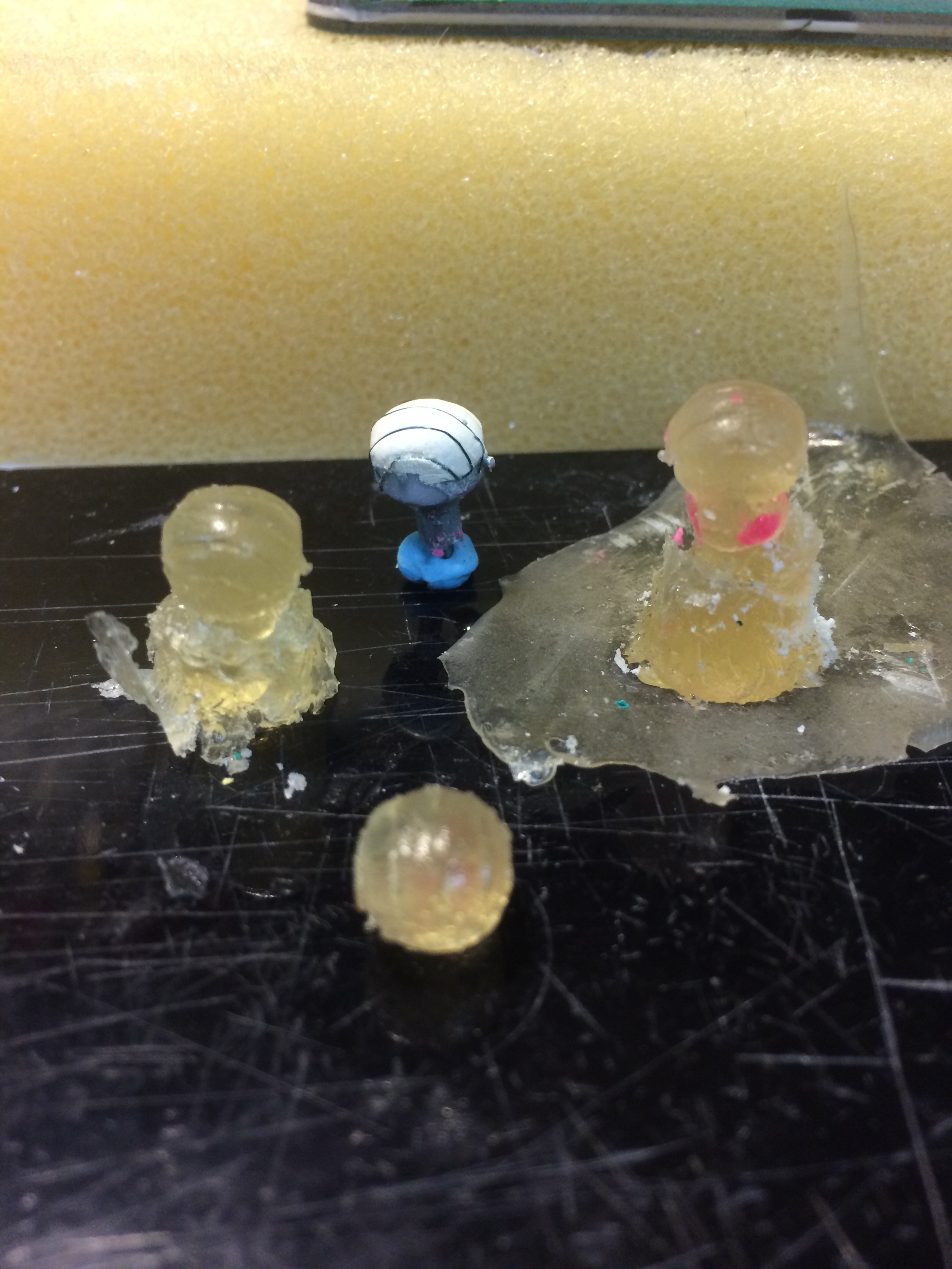
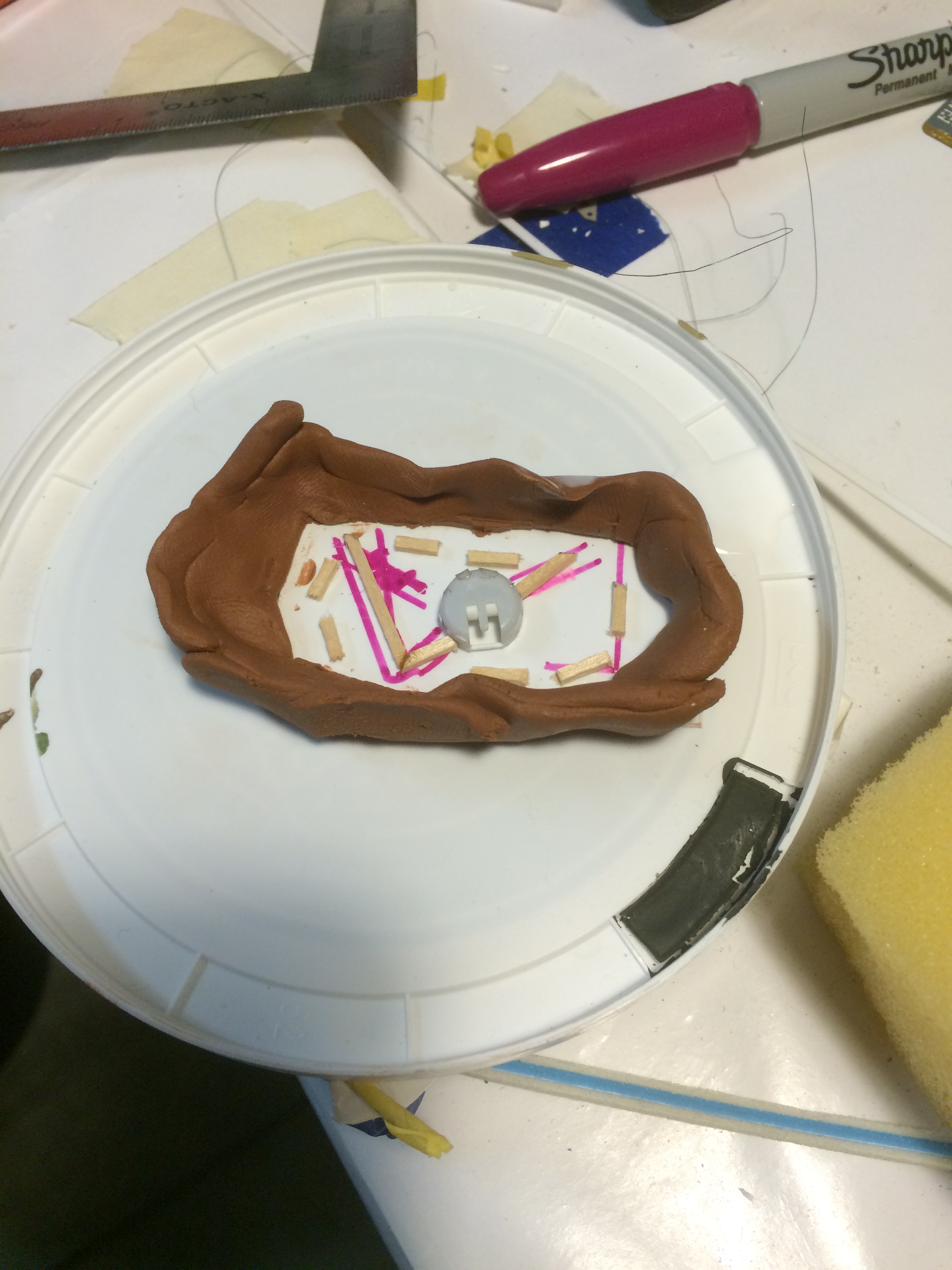
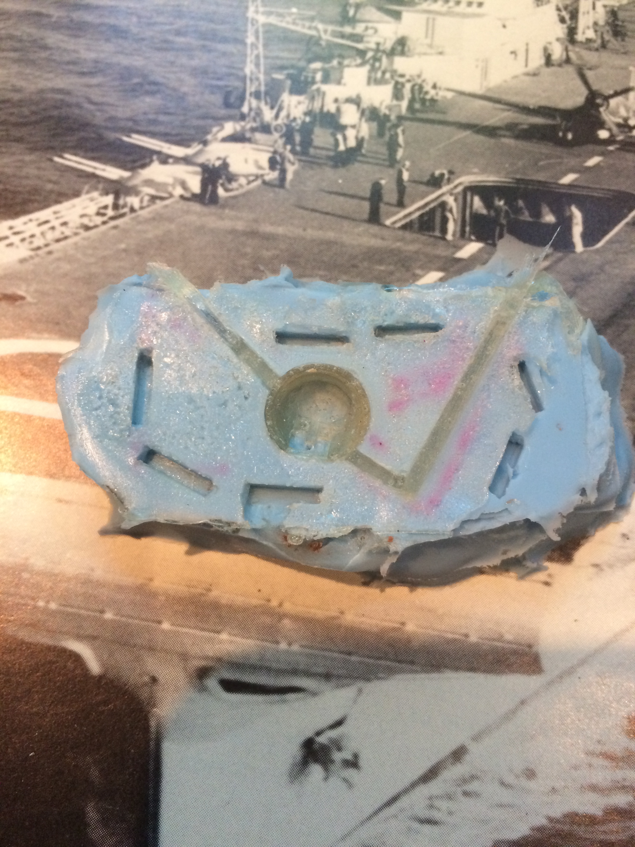
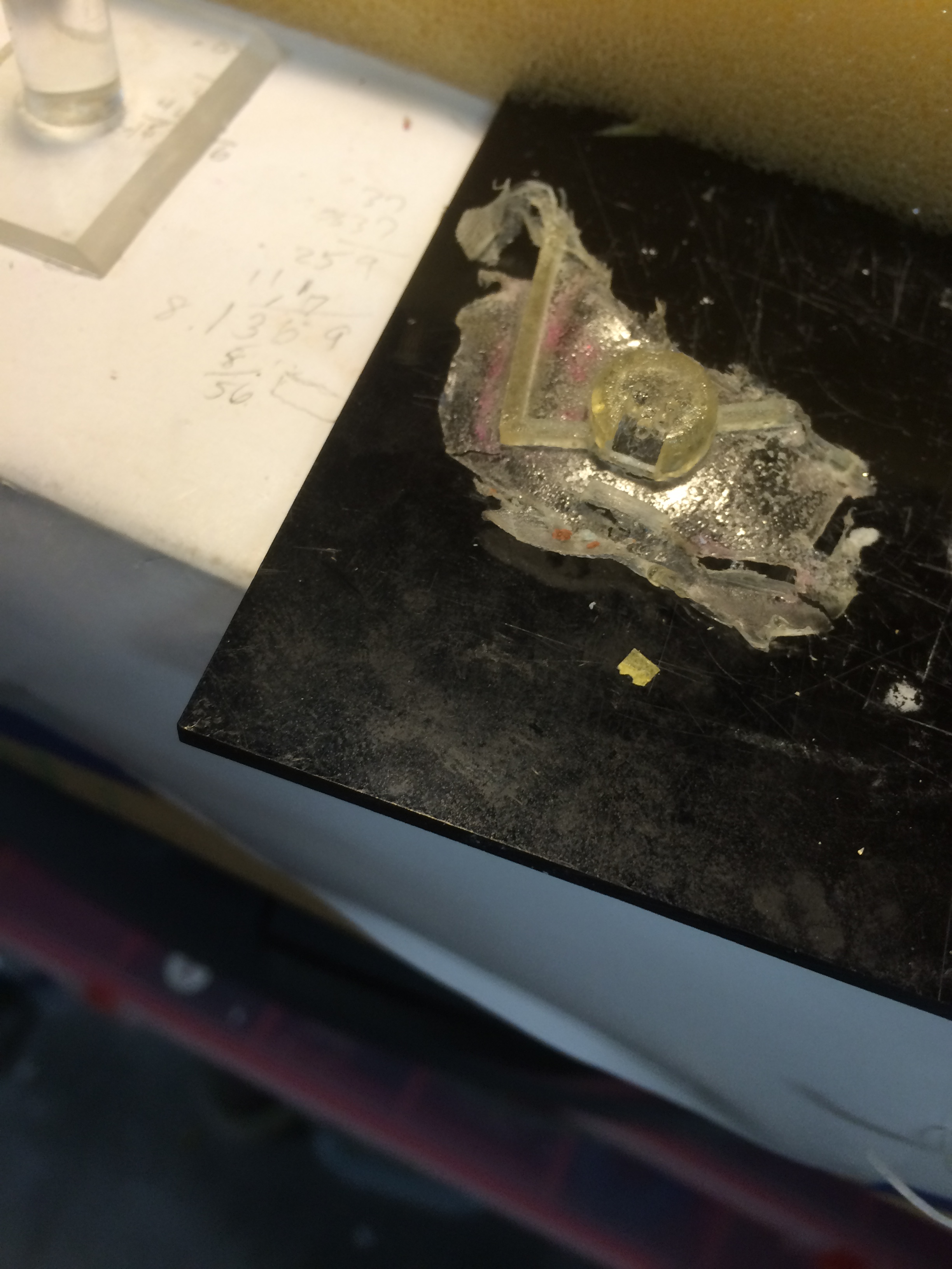
Now, painting the collector ring. I eventually ended up using miniature rubber washers with a 4mm inside diameter as shown below. Note the cutout made on the inner ring to accommodate the exhaust.

Swordfish Masking the cowling

I used Citadel Bronze acyrlic paint and got an OK result across all fifteen aircraft.

Swordfish collector ring

As per plan, I wanted to decal before assembly so I started with the tail fins.  The Starfighter 1/400 FAA decals for the tail fin stripe were too wide so they had to be carefully sliced along the red and blue bars to make the blue-white-red stripes of equal width.  In addition, there is a slight angle at the top to match the rudder polygon.  The first tail fin took me 15 minutes but I got faster and could do one every 5 minutes or so.  You can see the results here:

Swordfish Tail fin decaling

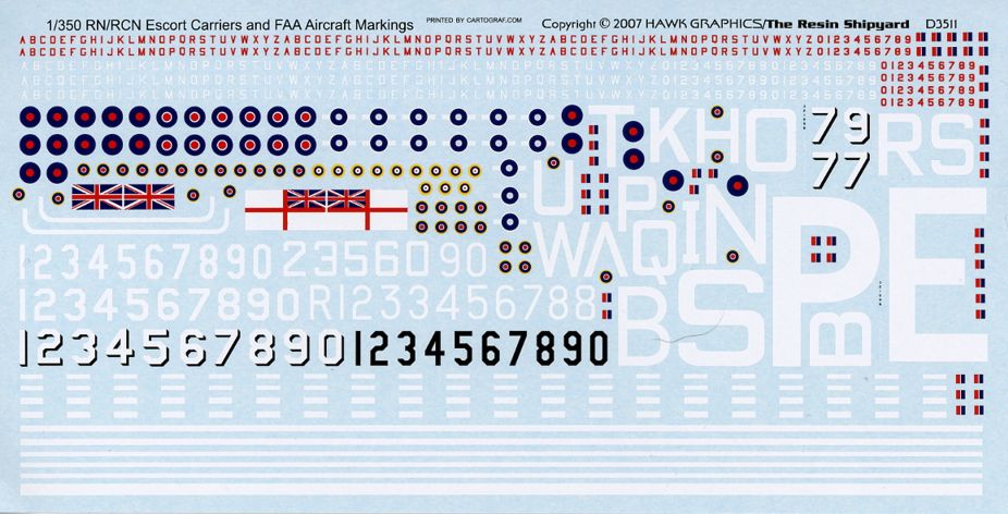
The Starfighter 1/400 roundels are too small by about 10-15% for the upper wing so I ordered some 1/350 roundels from Begemot in Ukraine. These just arrived and, unfortunately, they are even smaller than the Starfighter 1/400 roundels and are printed off-register (badly so). Plan B is an order (pending) to Hawk-Graphics for their 1/350 FAA decals but the proprietor said deliveries could take several weeks-to-months (!).  Plan C is to try making my own decals.

To get ready for Plan C, I used Inkscape, an open source vector graphics program, to try my hand at roundel making of the proper size.  It turned out that for the L’Arsenal Swordfish, it looked like 0.13″ diameter would do the trick.

Swordfish Roundel sizing

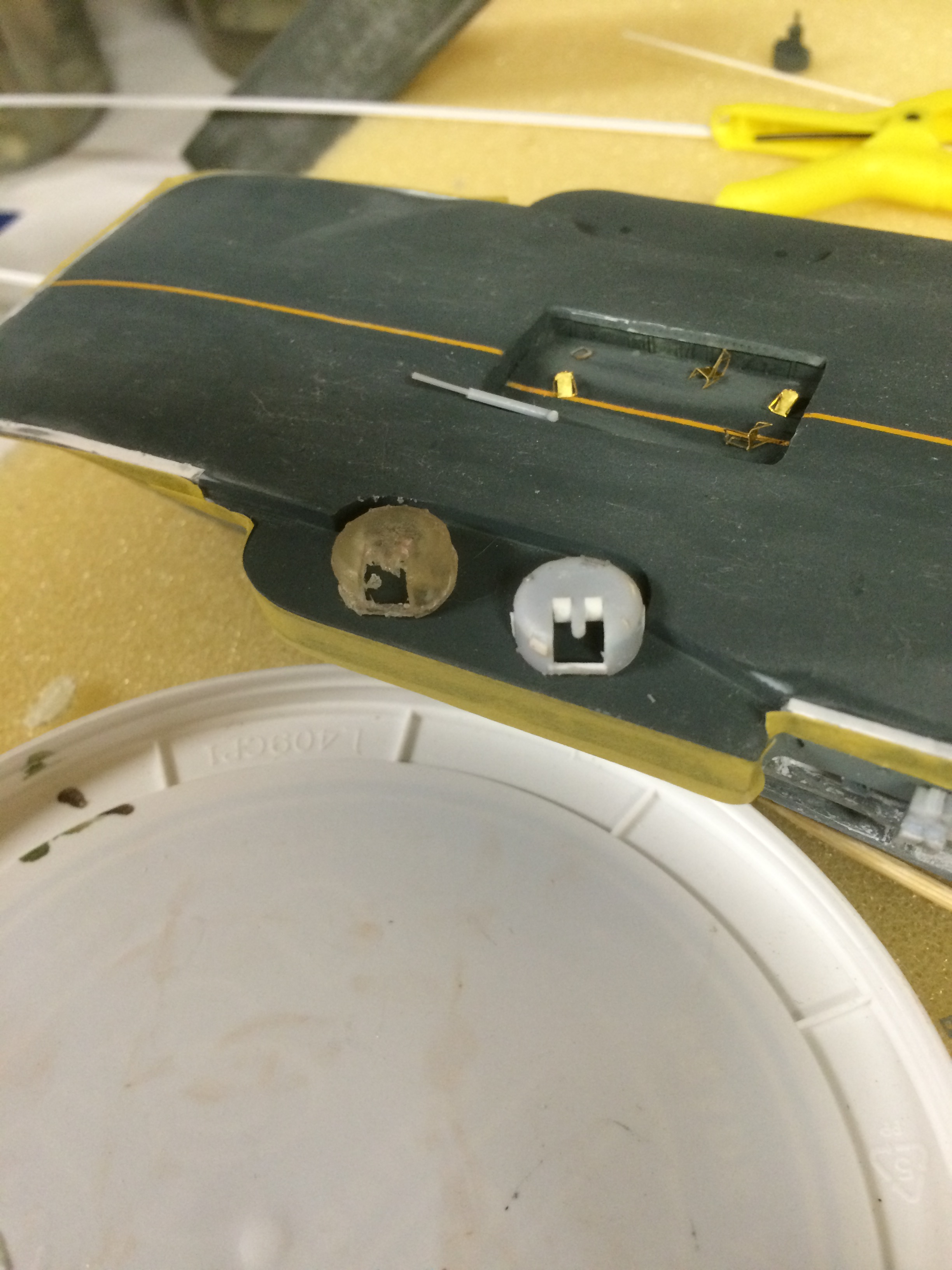
The color values for the Starfighter roundels don’t look right, color-wise either. They certainly don’t agree with the colors in Airfile Fairey Swordfish or Fleet Air Arm Camouflage and Markings. The red has too much pink or magenta in it. You can see this discrepancy in this photo (port side, Starfighter decal is on the left, proper size and better color is to the right). I’m still working on getting the colors to look right with repeated passes between computer and printer. And of course, on decal paper, more iterations may be required.

Swordfish decal sizing

 The grainy image comes from the light reflecting off the Future and I assume will be gone once I apply matte finish to the wing after assembly

As much as I was trying to avoid Plan C, I realized that the Archer Dry Transfer miniature numerals for the tail numbers were the wrong font (too short, too wide). This means I have two options:

i) Forego the tail numbers altogether (sad)

ii) Print my own tail numbers as decals.

Option ii) is tricky. For the gray tail fins, the tail number was black so printing decals on clear decal paper is plausible. But for the dark slate gray tails, the tail numbers were white and since I don’t have or want an ALPS printer, I’ll need to print on white decal paper by printing the surrounding area to match the paint color already on the 1/400 models.  This is going to mean several iterations to get a color match that will fool the eye. I am not looking forward to this.

Forging on white option ii), I did some sample backgrounds at various RGB values with the requisite tail numbers:

Swordfish white letter w background

As an aside, there are some interesting web sites with RGB values such as the one on Club Hyper.  These provide good starting values but ultimately, what I print has to match what I painted.  So, after taking my Dad’s Canon Pro 9000 Mk II photo printer, I printed the above on white decal paper.


Anyway, back to Plan C – making my own decals.

  • Attempt #1 was a complete failure. Using Micromark clear waterslide paper, I got a good print and following the Micromark instructions, immediately sealed it with 3 passes of Krylon Crystal Clear 1303A (that I also got from Micromark). I put this aside to dry. When I cut out a decal, and placed it in water, the colors immediately ran.  Research then ensued.  One model RR thread suggested spraying the decals very lightly once, setting aside for an hour, and repeating. A different poster says spraying never works. The same thread has a suggestion for using Evans Designs waterslide paper that needs no sealing coat. I’ll put the latter idea in my back pocket.
  • Attempt #2 was inspired by a Canon printer forum thread pointing out that the 9000 Pro uses dye inks that don’t need sealing, just a period of time to dry. I’m going to go for 24 hours. I noted on some test prints on non waterslide glossy paper that the ink was color fast and needed no sealing (I ran tap water over it).  Now, what I don’t know is whether the dye inks will sink into the Micromark water slide paper as they do for photo paper.  So, 24 hours later, I applied some water to an image and … it dissolved the color immediately. Oops
  • Attempt #3 was a repeat of the above except waiting a few hours, then sealing with a light Krylon coat, waiting another hour, another light Krylon coat, and then waiting overnight.  This actually worked until I realized that I had mistakenly printed the decals on white decal paper instead of clear.  So, another sheet was prepared on clear and the overcoating process completed.  I’ll test it tomorrow.

And, ta-da, attempt #3 worked well. Decals were colorfast.  The center red roundel has some opacity issues when applied over a dark upper wing but I can live with it.  The miniature tail numbers came out well as you can see in the picture below (before dull coating). You can also see the 65 gallon extra fuel tank in the torpedo-carrying planes (e.g. 5A, 4H, 5H)

Swordfish w tail numbers

Swordfish with tail numbers


Posted in Heller HMS Illustrious, Kit Building | Tagged , | Leave a comment

The smell of mold

The Heller kit comes with pieces for six HADT (High Angle Detector Tower) but at the time of Taranto, the Illustrious only had four.  The kit also includes some crude pieces for Type 285 radar that would go on top of the HADT. But, once again, these weren’t deployed on Illustrious at the time of Taranto. While the White Ensign Models PE radar set for Illustrious are nice looking, they were irrelevant. This created a dilemma for me as the HADT kit pieces are delivered to the modeler with mounts for the radar.

I briefly considered drilling out the top of the HADT and superdetailing it to look like this picture (minus the radar). However, the practical aspects of drilling out something with scale-like sides (despite purchasing a hole cutter bit for my Dremel) gave me pause. I didn’t even consider building four HADT from scratch.

HADCT

So, I decided to put a cover on the HADT similar to the one in this picture (see the right side of the first photo or the one taken from a visit to HMS Belfast – second photo):

HACS cover detail port sideHACS Cover

Step one was to build a pattern from Milliput plus 38 gauge wire to simulate the ribs in the cover.  Then I would create a mold and cast three more covers using epoxy resin.  Here is the pattern mounted in a small dish:

HADCT Mold Master

For the mold, I used Micromark’s Composimold – you heat it up in the microwave and pour it over the pattern:

HADCT Mixing the mold materialHADCT making the mold

After the mold cured, I removed the pattern and then mixed up TAP Plastics 1:1 epoxy resin.  I poured it into the cavity and then came back a few hours later and removed the casting.  This didn’t work out really well because the pattern was too deep in the Composimold and hence each cast was hard to remove.  I changed the placement of the pattern in a new batch of Composimold like this:

HADCT Mold #2

This worked out better and I poured resin in successive sessions. The results weren’t bad:

HADCT results

Quite a bit of cleanup was required.

Aside: This was my first attempt at molding and resin casting (ever).  I now have tremendous appreciation for resin aftermarket manufacturers who need to a) create perfect patterns, b) repeat step (a) several times when the set requires multiple instances of the pattern (like four HADTs), c) pour perfect resin mixes without bubbles, and d) rinse and repeat for each set to sell.

Well, with this under my belt, it was time to move onto the eight (8) 4.5″ turrets. The kit parts are simplistic in the extreme without any detail at all and a cavernous interior that would be all too visible to the unaided eye.  So, I created a new pattern for the turret with an eye to molding seven duplicates.  This time, I would make a two-part RTV mold per instructions with the molding material from Micromark.

The pattern was made from carefully cut out tiny pieces of 0.01″ styrene that after gluing, was sanded down to not have so much relief.  Here’s the pattern on the base of its mold box (note the channels to pour in resin and allow resin and air to escape built from basswood):

2015-09-18 21.20.21

The next step was to pour in the first half of the 1:1 RTV mold (this is really messy):

2015-09-18 21.36.53

After curing, I removed the pattern (note the locator points for the second half of the mold):

2015-09-19 15.44.14

I built up the mold box somewhat higher and then reinserted the pattern followed by pouring in RTV into the second half of the mold. The RTV doesn’t stick to itself but you definitely need mold release agent on the pattern and mold box (made of modeling clay)

2015-09-19 16.26.38

And here we have the two mold halves:

2015-09-20 14.19.40

Some cleanup to the mold was made with a sharp X-acto knife and then it was time for the epoxy resin.  I decided that pouring resin down the channel was not practical as the channel has a narrow cross-section and resin is really thick. So, I poured a small amount of resin into the cavity of the bottom mold and then pressed the top mold into the bottom mold using the locator pins to ensure an accurate fit. This is apparently called squash molding.  After waiting for the resin to cure (not enough time on my first attempt), I separated the mold halves and removed the casting (the right-hand picture is from squash mold #1 when I used too much resin – I had less runoff on try #2):

2015-09-26 14.20.172015-09-26 14.25.40

And here I show the pattern versus the casting:

2015-09-26 14.44.36

I wasn’t happy with the results as I realized the RTV mold wasn’t good enough to be accurate (the tongue separating the two gun barrels didn’t really work in the mold). Since making a new mold would be time-consuming, I decided I would manually replicate the detail with styrene on the other seven turrets. This would be tedious but would have predictable quality.  An additional motivating factor was that the resin casting needed cleanup and that would be a lot of time spent – possibly erasing the cast detail with sanding!

Were I to do this again, I would use coloring to the resin to make it easier to see the results and try it on larger pieces with less complexity (it is interesting to note that the Micromark instructions cast a model RR bridge side without any curves or delicate appendages).  Obviously, more skilled modelers could do better.  But this project needs to finish in my lifetime.

The real answer of course is 3D printing – design the master, replicate in software, and then print. If the master isn’t accurate, tweak it in software.  Not cheap but in theory, predictable and repeatable. Someday, someday.

Posted in Uncategorized | Tagged , , | Leave a comment

All Bands on Deck

Don’t try this sequence at home. It didn’t go well.

With the hull all built up, compartments installed, and quarterdeck and cable deck installed, it was time for the flight deck to go on. I saw this as a critical step towards feeling I would actually finish this project. Why, with the deck installed, all that would be left would be to add the island, and all of the various details in plastic and PE.

So, first I decided it would be easier and safer to paint the deck prior to gluing to the hull.  Step 1 was to lay down a yellowy-orange center stripe. There was no way I was going to use the kit-supplied decal – for one, it was white, and two, it is really long and I knew I’d mess it up and twist it or get it out of alignment. And a misaligned center stripe would be oh-so obvious a distraction.

The picture below shows some basic masking to lay down a stripe (width not important) of the yellow-orange color.  Based on photos, it looked like it was close in hue to the yellow of the roundel on a FAA Swordfish. You can see I used household masking tape here, imagining that I would peel it off within an hour or so.

Deck - masking the center line for painting

I had real trouble getting the color right and it took several passes, even over a white base.  Due to other commitments, I left the tape on a long time (as in weeks). When I finally did remove the masking tape, I discovered it had left a residue (big surprise) and much sanding was required.

I then applied  0.7mm Aizu masking tape over the yellow stripe in a very carefully marked-out straight line. Much burnishing was done to prevent (I hoped) bleed-through. The tape performed well for something so narrow.

Step 2 was to paint the deck using Colourcoat AP507A Dark Grey. The picture shows me midway through the painting process. Fortunately, I had loaded up on Colourcoat before White Ensign Models decided to pack it in. I was a bit too far away with the airbrush on the initial pass so some sanding was required with Micro Mesh pads to smooth out the surface.

Deck - painting

Step 3 was to remove the Aizu tape and see if the center stripe was as hoped for or marred in some way (as expected). Here you see me peeling back the tape. So far, so good…

Deck - unmasking

Terrific – it actually came out 100% good-enough!

So, now I could glue down the deck and then deal with any touch up issues like seams.

First of all, I should have glued on the deck before painting the deck but I was so concerned about getting the center line right and not accidentally overspraying the (already-painted) hull sides that I felt the deck needed to be painted off-the-hull.

As things turned out, despite multiple dry fitting passes, the deck-to-hull join left a lot to be desired. There were several reasons for this:

  • I had sawed off the keel to make a waterline model. This meant that the hull sides, when glued, weren’t exactly in the 3D space as Heller had intended.
  • I had mucked about changing the location of platforms and compartments to conform to the plans. This affected structural integrity and probably altered the deck-to-hull fit.
  • All of that resin, styrene strengthening bars, and plating to cover the sticky resin no doubt pushed parts of the hull in or out.

All in all, the deck didn’t fit well at all. I had to glue down sections at a time using a Touch-N-Flow liquid cement applicator and lots of clamps (mostly rubber bands – see post title).

Deck - clamping

Deck - gluing

Once the deck was secure, there were all sorts of gaps and seams to fill. On some sections of deck length, the hull was somewhat lower than the flight deck (0.10 inches). I used both styrene strips and Perfect Plastic Putty. Much retouching of paint looks to be in my near future. The worst spots were at bow and aft, as shown below.

Deck - putty

Posted in Heller HMS Illustrious, Kit Building | Tagged , | Leave a comment

Hide Me If You Can

(This post not strictly in build sequence from previous post)

Well, how does one paint the hull camouflage for the Taranto 1940 attack?  A clear picture taken on the days immediately prior to the attack would be helpful. I could find no such picture. Some informed deduction that would pass the straight face test would be the goal.

Initially, I discovered Profile Warship 10 that included on page 228 of a full color side starboard image … as she appeared when she launched the Fleet Air Arm attack on Taranto, 11 November 1940.. This image was drawn by T. Brittain and M. Trim. Here is an excerpt (trying to be respectful of copyright):

Hull Warship 10

As you can see, a monochromatic gray.

I next saw a post from noted Royal Navy and Fleet Air Arm researcher Ian Gazeley:

Illustrious arrived in the Mediterranean in overall (medium) grey. Although there are very few photographs, I’d speculate that two distinct ‘Alexandria’ type schemes may have been were applied after she arrived in the Med. The first shows less contrast than the scheme worn at the time of her extensive damage on 10/1/41. This would be consistent with the dates recorded above, with the first scheme applied in September 1940 and the second in December 1940. It appears from the photographs I’ve seen that the repainting in February 1941 followed the same pattern as the December 1940 scheme.

Gazeley follows up on this post on 2007-07-02 with:

What do you make of this image of Illustrious? It is supposedly, ‘returning from Taranto’ at Alexandria. If so, it is after her repaint at Alexandria in September 1940. The scheme shows much less contrast than the one worn in January 1941, following the December repaint, but generally follows the same pattern.

Unfortunately, the URL no longer resolves to a photo

Further research has this posting by Laurence Batchelor 2007-07-02:

Do my eyes deceive me or am I seeing faint patterned camouflage?

My impression has always been Illustrious was dark grey overall for the convoy operation and subsequent Taranto raid.

However I have seen this pattern shown before and evidence that it was on her in 1940 and shown on her whilst returning to Alex from the Taranto raid.
This has been a lingering dilemma which I never fully researched to resolve.

More uncertainty came from Alan Raven’s book Warship Perspectives Camouflage Volume One: Royal Navy 1939-1941 that has a drawing of Illustrious with disruptive camouflage and the caption ..

this pattern was carried from late 1940 until the completion of her refit in the UK in 1942.

This would tie in with Gazeley’s date of 1940-12-14. Maddeningly, Raven says nothing about the first Alexandria painting mentioned by Gazeley on 1940-09-20/26 as that covers the Taranto period.  Furthermore, the disruptive camouflage is just that – sharp edged. A fragment of the image (again, copyright respectful) is shown here:

Raven Illustrious Alexandria camouflage

Video footage of Illustrious entering Malta in January 1941 did not indicate much camouflage at all, if any.

Illustrious 1941 Malta Starboard 2

Fortunately, one of the posters on The Ship Model Forum, “dick”, led me to video footage of October 1940 convoy cover operations prior to Taranto.

Here is a screen cap:

HMS Illustrious med Oct 1940 - AWM screencap

If you click on the image to see in a larger size, you can see that Illustrious is not in disruptive camouflage.  This is what I decided to go with.  And, I could be wrong but time to move on.

With my trusty Colourcoat paints, I used 507A, 507B, and 507C  with as best a representation as I could discern of the video’s camouflage demarcation points.

Hull painting 1 Hull painting 2 Hull painting 3

Posted in Uncategorized | Leave a comment

You light up my deck

With all the detail I was putting into the cable and quarter decks, I knew that with normal lighting, no one would be able to see said detail.  So, I decided to do my first LED lighting add-on. But, I get ahead of myself.

Using the Hatton book, I tried to follow the plans. Initially, this meant replacing the kit’s cabledeck with a styrene deck that actually covered the entire space.

Cabledeck planFocsle Template

A lot of fiddling was required so that it would lie flat and below the cutouts. With the template in hand, I drilled out the anchor runs and then cut wood decking to go over my styrene deck. The wood deck vendor, scaledecks.com,  recommended painting the styrene before gluing down the thin paper to avoid any bleed through of the underlying white.

Cabledeck - wood

A similar process was done for the quarterdeck.

Cabledeck 1 Cabledeck installed

Above are a couple of views of the start and finish of the detailing. Anchor runs, bollards, compartments, winches, cable reels, signal guns (scratch-built), and miscellany are all included as I mostly followed the Hatton plan.  You can also see the L’Arsenal anchor chain I used.

Here is the quarterdeck (the brace is there for strength — except the first one I used was too long so I spliced a new one. Ugly, but it won’t be seen once the deck is on).

Quarterdeck installed

And some detail of scale with 1/400 crew..

Cable deck chain and signal guns Quarter deck rafts and vent

Here are both decks installed:

Wiring - ready to seal it up

You can see the deck ceilings have been detailed as well (they are lying amidships).

Now, time to light up.  I found a great resource on LED lighting for model ships and decided that I only needed two LEDs – one for the cable deck and one for the quarterdeck. The circuit would be series, not parallel. There was no way I could replace a bulb if it went out (as it would be beneath the flight deck) regardless of the wiring approach so series was good enough.

I purchased wiring, shrink tubing, and LED lights from Evan Designs.  They provided all the specs on forward voltage ratings of each bulb so I could calculate the necessary resistor (purchased from Radio Shack – they probably hadn’t had anyone come in and buy resistors since 1990 – sadly, they are now bankrupt).

Where to put the bulb?  I decided that to avoid being obtrusive, I would mount the bulb from above and towards the hull center for each deck. I cutout a styrene ceiling for each deck that would avoid light bleed-through.  Here is the one for the quarterdeck:

Quarterdeck template

The trick would be whether there would be enough or too much light upon the interior details. Step Zero was to verify that my circuit even worked. All systems go!

Wiring - testing the circuit

Step One involved soldering all the wires to LEDs and then protecting the joints with shrink wrap tubing. I used a heat gun to do this but carefully shielded the model with card board to avoid the heat gun melting the ship!

Wiring - Heat shrink

Step Two was to see if there would be adequate light given the location of the holes I had cut into the deck’s ceiling. I had to think about how far into the hole would I extend the bulb, if at all.

Quarterdeck unlit Quarterdeck lighting test run

The picture on the left is before illumination. Sure is dark in there.  The picture on the right is based on the initial test of placing the bulb atop the cutout hole. Note I haven’t secured the ceiling yet, just tacked it in place. Hmm. still a bit too dark.

Wiring - final check before gluing the cabledeck ceiling Wiring - cabledeck - a bit too bright Wiring - quarterdeck - a bit too bright

I tried again, this time placing the bulb deeper into the cutout. The first picture is unlit, then the latter two are with the switch turned on. Too bright I would say – looks like a super nova exploded nearby.

To split the difference, I decided to paint the bulb with a thin light color to cut down on the lumens. This worked well.

I then secured the wiring, running it through the keel (previously  prepared for this) and retested to make sure I hadn’t broken any of the delicate fine gauge wires.

Posted in Uncategorized | Leave a comment

Not resinating

One thing I learned on the Albemarle project was the importance of securely attaching components before their entombment inside of larger elements. If said component detached, they would rattle around inside and be impossible to re-attach. The project would be ‘ruined’.

For the Illustrious, this would mean that anything inside the hull+flight deck could not ever detach, no matter how vigorous the model was handled (like aggressive sanding or even ‘drops’).  As the compartments along both inner starboard and port sides would, per instructions, be glued to the hull walls, there was always the possibility that the glue butt joints would fail.

So, I decided that the solution would be to fill the hull with resin up to the bottom of the compartments so their would be not only butt-jointed attachment points to the hull sides but there would be a glue-supported gravity joint between the bottom of the compartment and the top of the resin pour.

Before the resin could be poured, I would need to install conduit for the wiring to light up the cable and quarter decks.Wiring 1

The wiring then fed out the bottom of the hull as shown here (there will be a full post on the wiring later)

Wiring 3

You can see in the first photo that I built some bulkheads for the resin pours as each compartment was at a different height. These bulkheads would need to be liquid resin-tight as otherwise the pour would get all over the place.

I used Micro Scale LiquiTape to temporarily mount the compartments (except for one compartment where I idiotically used liquid cement).

Resin before 2 - sticky

Here you can see everything temporarily mounted so I’d have a good idea as to how high to pour the resin within each inner cell.

Resin before 5

Using resin from MicroMark, I followed the instructions and mixed up 1:1 portions.

Resin pour 2

And let the pouring begin!  You have to work quickly as the resin will quickly harden.

Resin pour 1

or not ?  Note the cloudiness after a few minutes.Resin pour 3

Up by the cable deck, it was even worse – the resin never hardened.

Resin pour 4

I waited a week – the resin simply never cured. It was viscous, very sticky to the touch, and if you tipped the model slightly, the resin would start flowing.  Even worse, it had leaked out of the bottom, not so resin-tight gapsResin after 1 (disaster)

So, what was the problem?

Obviously, I should have experimented before pouring into the hull. I decided the causes were either:

  • The Micro Mark resin (although never opened) was too old – I had bought it more than 4 years ago
  • I didn’t mix it thoroughly enough, perhaps frightened off by the package warnings stating the pour life was extremely short.

Regardless, I had a real mess (and a sticky-tacky mess at that) on my hands.  Even after a month, the resin was gummy and gooey.  I couldn’t dig it out as it was bonded to the hull sides and bottom.

The eventual solution was similar to how we deal with nuclear waste – bury it under an impermeable surface.  After soaking up the liquid elements using lots of  paper towels, I ended up cutting to size various .06″ styrene sheets to sit atop the tacky resin messes in each hull cell.  Thus, any handling of the model during construction would have my fingers touch pure styrene rather than gloppy guck.  This took a while as all the cells are shaped differently.  You can see some of the work here:

Sealed off hull cells

All of the gaps where the sheets wouldn’t cover were filled with extra thick CA glue. Paper towel remained stuffed in some places for weeks, wicking out the last of the moisture. When done, the model was now ready to handle, no longer leaked, and as a side effect, quite heavy.

As an aside, I experimented later in one of the hull cells (cable deck) using recently purchased TAP Plastics resin. I really mixed it up well (I think their instructions were better – reminding me to scrape the cup insides as well as stir).  A pour was made and it cured as expected.  Live (hard) and learn (hard).

Resin retry 1

Posted in Uncategorized | Leave a comment

Dollhouses

Dismayed by the thought of making a couple of hundred rigols, I switched attention for a few weeks to the business of the exposed interior spaces. You can search high and low for photos of the hull openings on both port and starboard sides where the ship’s boats were stowed, the ship’s refuse was dumped, and where the air vents into the hangar deck were placed.  You’ll find nothing as these spaces were in shadows to the camera and from the distance and angle of the camera, no detail emerges.

The Heller kit is completely silent on this topic, presenting the modeller with slab sided open boxes.  Fortunately, I had two resources – the Hatton book of HMS Victorious plans and photos from the HMS Indomitable builder’s model.  Hatton has scale 1/250 and in some cases, 1/100 drawings (mostly plan views, a few profiles) of these compartments.

Hatton plan view - compartment

Boy, were they filled with detail, most of which was unavailable in photo etch or resin in 1/400 scale.  So, I set about scratch building winches, lockers, boat launching rails, and other geegaws.  I ordered a bunch of 1/350 and 1/700 accessories (vents, bollards, fairleads, life rafts) from various after-market suppliers. Some of these I shaved down to 1/400 scale; others I left as is.  But mostly, I ordered a lot of strip and rod styrene in every dimension from 0.01″ to 0.250″ strips and 0.01″ to 0.08″ diameter.

Using the plans from Hatton, I scaled down the 1/250 measurements to 1/400, marked the styrene, and cut with the chopper.  Somewhere along the way, while looking for images of winches, I discovered this website On the Slipway, by Evert-Jan Foeth. He documented an incredible build of HMS Hood in 1/350.  I want to quote from his ‘about me’ page:

As you might have noticed, actually finishing the model isn’t that important; I enjoy finding drawings, images and information needed to build all the components of the model. I then need to find out how to actually make all these small parts by learning new construction techniques. I enjoy building parts that are more detailed and precise than most smaller-scale models and I can easily spend more time on a small gun, launch or rangefinder than some people spend on an entire model. The amount of time spent on the model increases drastically, so as a result the entire ship model is slowly going nowhere.

As I read his fabrication endeavors for just the Carley Floats, I sighed that my efforts at mere styrene were like a middle school production of Hamlet up against the Royal Shakespeare Company at the Barbican.

One of the extra challenges was that the kit’s compartments, while they scaled out OK length-wise, they were not deep enough per Hatton.. So in many cases, I had to slice off the back and extend the depth of the box.  What a pain.

Here are some photos of the results. I opted to glue most of the adornments directly into the compartments and deal with the painting issues later (instead of trying to paint individual items and probably losing a few to the blast of the airbrush). The way I figured it, there would be no way to see if the back side of a bollard was painted once the model was assembled as the compartments are just too small to peer into (of course if one had a tiny mirror on a stick….)

CompartmentDetail

Floats, raft, catamaran

CompartmentDetail2

Refuse chute, work space, paravane mounts, hawsers, vents, ladders

Paravanes

Paravanes (from L’Arsenal – 1/350)

Compartments2

Winches and completed compartments

Compartments3

More completed compartments, lots of quarterdeck miscellany

I have the cable deck parts also done but this will be the subject of a different post.  Any one 1/400 facsimile is flawed in some way but the sheer number of elements creates a sense of busyness that does a good job overall to the eye.

In some future life, I will get rich making 3D printer versions of 1/400 winches, lifebuoys, bollards, paravanes, etc to that vast market of Heller 1/400 Illustrious modellers – no doubt just as some other kit maker comes out with a superbly detailed 1/350 version thus depriving me of the $50 or so of sales.

UPDATE 2015-06-26

And, sure enough, long after I emplaced the compartments, NorthStar Models has some very nice 1/350 anchors and winches. You can use the anchors on the quarterdeck and the winches all over the place. Too late for me.

Posted in Heller HMS Illustrious | Tagged , , | Leave a comment

The Portholes of November

Time for the portholes (also known as scuttles). I decided to go for fidelity and would use Hatton’s book Anatomy of a Ship The Aircraft Carrier Victorious as a guide. This would entail filling some of the Heller kit portholes and drilling out new ones.  So, one weekend afternoon, I did just that on the starboard side. You can see the messy process here:

Porthole filling starboard aft Porthole filling starboard fore

and filled:

Portholes filled starboard

Avast ye erk!

Could I trust Hatton’s book?  He shows side views of Victorious as completed in April 1941, five months after Taranto. Something in the back of my mind said that there were more portholes on the Illustrious in late 1940 than on the Victorious in spring 1941. The Indomitable builder’s model was no help (it confirmed the Victorious drawings but Indomitable was completed after Victorious). So, I assembled a timeline of photos from the 1939 launch to her arrival in Norfolk, Virginia for refit after the January 1941 bombing off Malta. The timeline:

Two shots from the launch – first is from Pathe’s web site. The second is from the Vickers web site

Illustrious 1939 Bow Illustrious 1939 Port Stern View in dry dock

Uh-oh. I just filled these portholes on the model.  Maybe during post-launch completion and shakedown, they removed the portholes.  I could only hope for proof otherwise I would be undoing my work.

Then two unclear shots from 1940 before action at Taranto. The first from Plymouth and the second from Bermuda (via Fleet Air Arm Camouflage and Markings 1937-1941 by Stuart Lloyd, photo credited to Ian Gazeley page 88):

Illustrious 1940  Plymouth Sound port side much detail Illustrious 1940 Bermuda port view_edited

The Plymouth June 1940 photo, only five months before Taranto suggested that the stern portholes as launched were still present.

And lastly, the clinchers – scenes of Illustrious as she pulled into Malta in January 1941 (only two months after Taranto), then Norfolk a few months later. Both images capped from BattleFleet Royal Navy in the 20th Century Disk 1, Chapter 4.

Illustrious 1941 Malta starboard 3

Illustrious 1941 Norfolk port dock repairs

Thus armed with photographic evidence surrounding the time period in question, I re-opened the filled portholes, re-examined the photos in detail, marked new portholes, filled in a few errant portholes, and did this for both port and starboard sides.  Much work and probably not 100% accurate but considerably better than either the Heller kit or taking the easy route and applying the otherwise excellent Hatton Victorious drawings to the Illustrious ca. November 1940.

Portholes opened aft

Portholes opened fore

Portholes opened mid

Lots more work correcting the ship to go – notably the HACS (High Angle Control System) which seems to be misshaped/misplaced all over the kit.

Coda (2013-11-10)  By chance, I discovered another Heller Victorious build on the Internet that in turn referenced another supplier of 1/400 photo etch parts – North Star Models. Although they have a US distributor, the specific item I spotted were sheets of 1/400 portholes with and without ‘visors’ (also known as rainshields, eyebrows, and more formally, rigols).  The US distributor did not carry these portholes. So, a quick Paypal transaction and then two weeks later, this arrived:

Portholes from Ukraine_edited

So, my first ever letter from Zhitomir, Ukraine.  It is interesting that the package is labeled as made in Latvia (part of the EU) although shipped from Ukraine. No doubt some tax or customs issue.

Go to Project Start
Posted in Uncategorized | Tagged , | Leave a comment

“Can’t find my way home”

Here I shall show an example of my attempt to make the Heller Illustrious kit look more like the real HMS Illustrious ca. 1940. Near the bow are two searchlight platforms, one port and one starboard.  Let’s take a look at the problem.

Kit versus reality (yes, kit is starboard and actual is port but they were same on both sides:

Serachlight platform as molded 2
1941_05_20_illustrious_david_buell hull detail

What was Heller thinking?  Looks like they ‘factored out’ the complex shape into something that looked more suitable for a graceful aircraft carrier. I looked at pictures of Illustrious post war and even then the searchlight platform hadn’t really changed from 1940.

After much thinking about how to approach the problem, I turned to the razor saw to remove the molded solid platform + support structure: Searchlight platform remove 1

I also needed to remove the existing platform which was too thick and the wrong shape from the plan view. The trusty Dremel made quick work of the coarse work, then I finished with a file and sanding sticks.

Searchlight platform remove 2

With the cutting completed, time to ‘weld’ in some styrene to align with the rest of the hull (not a great welding job, some patching will be necessary):

Searchlight platform weld in styrene

I then took the 1/100 plan from Hatton’s book and scaled it in Photoshop to 1/400, printed, traced, and cut out a new platform. I glued in the new platform and could see that some gaps would need to be filled. Fortunately, this was more-or-less consistent with the deck plan view that showed the kit had recessed the platform too far inward.

The second photo shows how I approached filling in an arc. Rather than fill from the outer edge of the arc trying to create an inner ‘arc’ that matched the outline of the platform, I cut a strip of brass sheet and folded/rolled it to get the inner ‘arc’ shape I wanted.  Some superglue and then I could stuff the space between the brass and the deck with miscellaneous styrene bits that would be sanded down to deck height.  You can also see in the photos the awful fit between hull and deck that will require delightful filling, sanding and paint touch-up much later in this project.

Searchlight platform gaps to fillSearchlight platform gap fill step 1

In a bit of inspiration, I decided to make my own photo etch for the support gussets from the hull upwards to the platform. That will come later in the project so hang tight for what will no doubt be an interesting photo etch ‘lab’ experience (something I’ve never done before)

This should be fun, next up is counting holes

Go to Project Start
Posted in Kit Building | Tagged | Leave a comment

Fool’s Errand?

At this point in the project, i realize I have my injection-molded styrene cut out for me (well, actually, I will have to do the cutting up of the hull and deck in order to replicate the 1940 Illustrious). Why bother? Why not build the kit out-of-the-box and focus on painting and the seascape?  Certainly my family wouldn’t know that the searchlight platforms are shaped incorrectly in all three dimensions. Or that the portholes are in the wrong locations. Or some of the ship’s boat decks are incorrectly sited.

I’ve reflected on this and come to these observations:

  • Other modellers have set the bar high for accurate renditions of their prototypes (i.e. the real object) and such modellers publish their results to acclaim. As I’m writing this blog for anyone to encounter, I should put my effort consistent with my public mouth.
  • I’ve always been inclined towards deferred gratification so spending a lot of time on a project is agreeable provided the end result is worthy of the effort expended.
  • Once started down the road of fidelity, you can’t really stop. Reshape the searchlight platforms but not relocate the portholes?  This seems hypocritical – like only obeying some traffic laws.

I’m also iconoclastic. Yes, the projects are related to my family but I’m glad they are of subjects not well-covered by kits and other modellers (viz the Armstrong Whitworth Albemarle project and the forthcoming USS Shiloh, a Casco class Civil War monitor). If my family had some connection to Mustangs or Spitfires, I’m not sure my energy would be there to try and build these iconic airplanes knowing that there were superlative examples done by much better modellers.

I enjoy the research into less well-covered subjects. I enjoy publishing my experiences knowing that I might be able to help others doing similar subjects.  Let’s hope I can finish this in less time than the Albemarle.

OK, back to work.

Posted in Kit Building | Tagged | Leave a comment